Nintendo Console Modding
New Nintendo 3DS XL USB-C Mod
The goal of this project was to wire and solder a USB-C header to a New Nintendo 3DS XL.
The first step was to take apart the 3DS shell and disconnect all the ribbon cables to separate the motherboard.
After measuring the voltage of the charger to find the positives, negatives, and grounds.
I placed new solder under the header to remove the old AC adapter header and then removed the excess with a solder wick.
I cleaned the space with alcohol and marked the positive and negative points.
Using a USB-C breakout board I checked which pins were viable and soldered a copper wire to it. I then used UV glue to keep the wire in place.
I then soldered the USB-C in place of the old AC adapter header and soldered the copper wire to the positive.
After checking that the device would boot with the battery back in place, I widened the shell charging hole with a dremel.
For the final step I powered on the device and verified that the device charged with the USB-C cable.
Nintendo Switch Mod
This project was for a client who wanted their Nintendo Switch modchipped and its “Joy-Cons” to have Hall effect sensors.
The main aspect that would make this project difficult was that their Switch version used the “Mariko” SoC which means it wasn’t vulnerable to a simple firmware exploit. This meant I would have to tackle a difficult soldering project.
I decided to first tackle the Hall effect sensors installation as it would be easy. I replaced the old joysticks with new Hall effect ones and calibrated them in the system.
In preparation for the modchip install, I used a USB-C ribbon cable connector to connect the modchip to my PC and ensure that the UF2 files were installed.
I then took apart the switch and disassembled it entirely including cleaning off the old thermal paste and heatsink.
I first pre-tinned the flex cable for the modchip using 0.025″ leaded solder and flux.
I put the flex cable in place and tediously microsoldered it to the correct caps.
After succesfully soldering the caps to the ribbon cable it was time to replace the eMMC module.
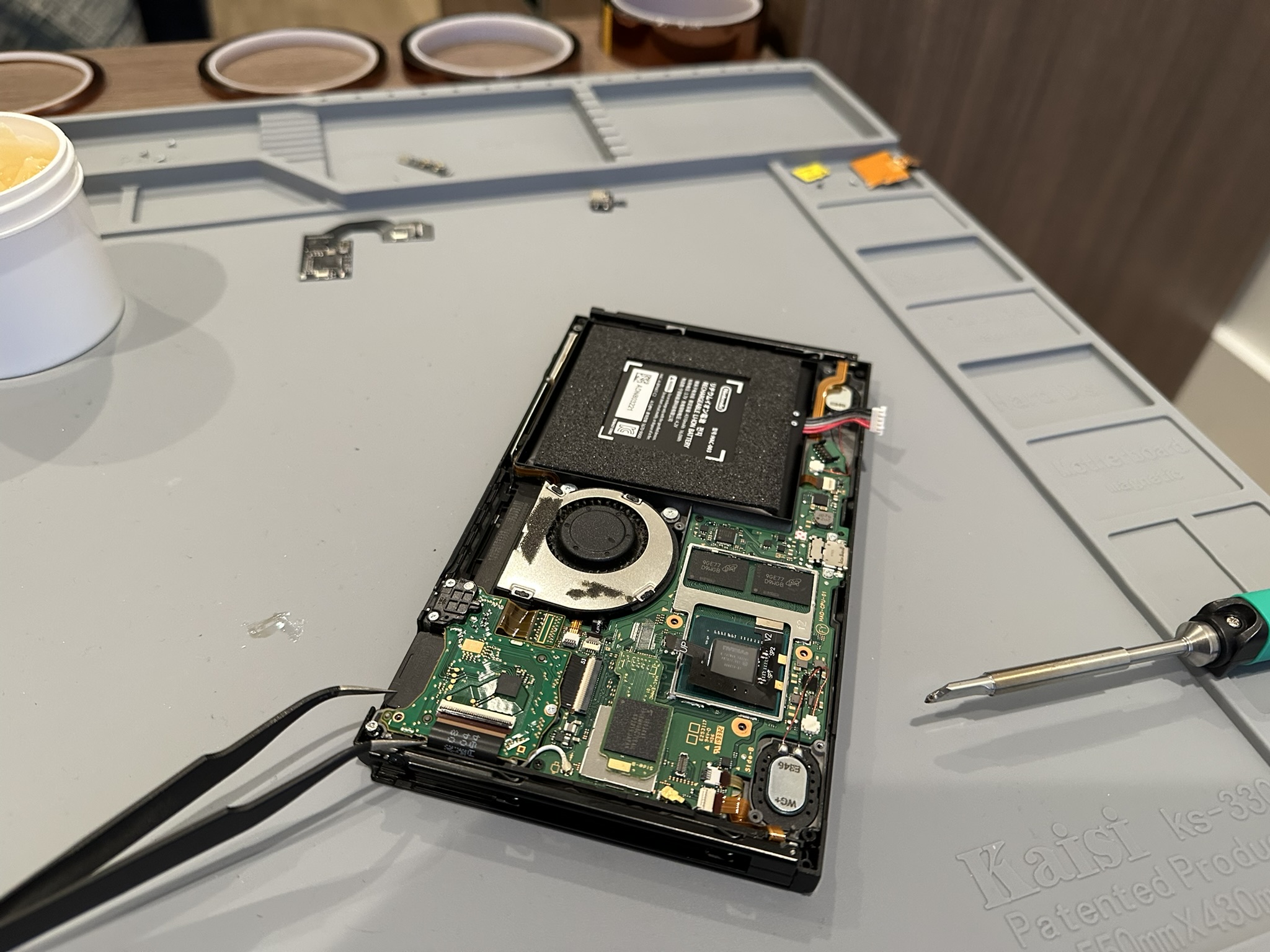
I removed the eMMC module, connected the picofly modchip to its port as a middle-man, and connected the eMMC to the modchip.
Before closing up the system I made sure the Switch powered on properly and the flex cables properly made contact to the caps.
I then closed the system by reappyling new thermal paste and modifying the heatsink to accomodate the new flex cables.
I protected the device from shortages by applying polyimide tape around the heatsinks and screwed the shell back together.
Now that the hardware was finished all that was left was to boot the client’s micro SD card with their desired software and give it to them.